Brief introduction on Electromagnetism
To create a magnet or magnetic field, we are going to have to look at how they are generated. The relationship between current and magnetics field behave according to the right-hand rule. As current passes through a wire, a magnetic field forms around the wire in the direction of your fingers as they wrap around it. This is a simplification of Ampère’s force law as it acts on a current carrying wire. Now, if you place that same wire in a pre-existing magnetic field, you can generate a force. This force is referred to as the Lorentz force.If the current is increased, the strength of the magnetic field is strengthened. Though, to do something useful with the field, it would take incredible amounts of current. Furthermore, the wire delivering the current would be carrying the same magnetic strength, thus creating uncontrolled fields. By bending the wire into a loop, a directed and concentrated field can be created.
Electromagnets
By looping wire and passing a current, an electromagnet is created. If one loop of wire can concentrate the field, what can you do with more? How about a few hundred more! The more loops you add to the circuit, the stronger the field becomes for a given current. If that’s the case, why don’t we see thousands , if not millions, of windings in motors and electromagnets? Well, the longer the wire the higher resistance it has.
Ohm’s law (V = I*R) says to maintain the same current as resistance increases, voltage must increase.
In some cases it makes sense to use higher voltages; in other cases some use larger wire with less resistance. Using larger wire is more costly and is generally more difficult to work with. These are factors that have to be weighed when designing a motor.
DC Brush Motors
The DC brush motor is one of the simplest motors in use today. You can find these motors just about anywhere. They are in household appliances, toys, and automobiles. Being simple to construct and control, these motors are the go-to solution for professionals and hobbyists alike.
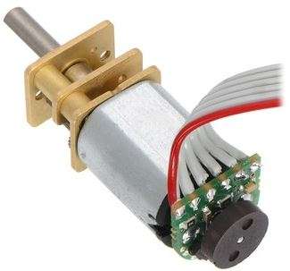
The Anatomy of a Brush Motor
To better understand how one works, let’s start by tearing down a simple hobby motor. They are simple in construction, comprising of a few key components.
- Brushes – Delivers power from the contacts to the armature through the commutator
- Contacts – Brings power from the controller to the brushes
- Commutator – Delivers power to the appropriate set of windings as the armature rotates
- Coils – Converts electricity to a magnetic field that drives the axle
- Stator – Increases the efficiency of the coils by focusing the magnetic field
- Axle – Transfers the mechanical power of the motor to the user application
- Magnets – Provide a magnetic field for the coils to attract and repel
- Bushing – Minimizes friction for the axle
- Can – Provides a mechanical casing for the motor
As the coils are energized, they attract to the magnets located around the motor. This rotates the motor until the brushes make contact with a new set of commutator contacts. This new contact energizes a new set of coils and starts the process again. To reverse the direction of the motor, simply reverse the polarity on the motor contacts. Sparks inside a brush motor are produced by the brush jumping to the next contact. Each wire of a coil is connected to the two closest commutator contacts.
An odd number of coils is always used to prevent the motor from getting locked into a steady state. Larger motors also use more sets of coils to help eliminate “cogging,” thus providing smooth control at low revolutions per minute (RPMs). Cogging can be demonstrated by rotating the motor axle by hand. You will feel “bumps” in the motion where the magnets are closest to the exposed stator. Cogging can be eliminated with a few tricks in design, but the most prevalent is removing the stator all together. These types of motors are referred to as ironless or coreless motors.
Pros
- Simple to control
- Excellent torque at low RPM
- Inexpensive and mass produced
Cons
- Brushes can wear out over time
- Brush arcing can generate electromagnetic noise
- Usually limited in speed due to brush heating
Brushless Motors [Powerful!]
Brushless motors are taking over!
Ok, maybe that was an overstatement. However, brushless motors have begun to dominate the hobby markets between aircraft and ground vehicles. Controlling these motors had been a hurdle up until microcontrollers became cheap and powerful enough to handle the task. There is still work being done to develop faster and more efficient controllers to unlock their amazing potential. Without brushes to fail, these motors deliver more power and can do so silently. Most high-end appliances and vehicles are moving to brushless systems. One notable example is the Tesla Model S.
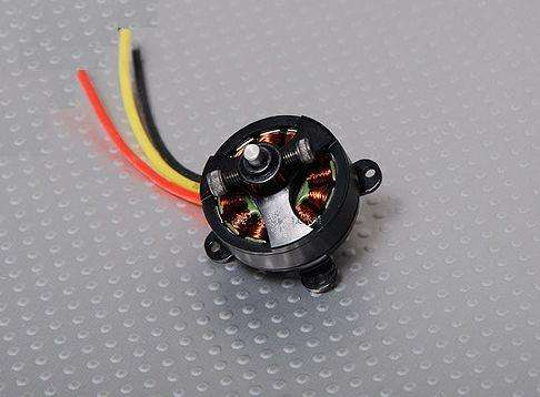
The Anatomy of a Brushless Motor
To better understand how one works, let’s start by tearing down a simple brushless motor. These are commonly found on remote control airplanes and helicopters.
- Windings – Converts electricity to a magnetic field that drives the rotor
- Contacts – Brings power from the controller to the brushes
- Bearings – Minimizes friction for the axle
- Stator – Increases the efficiency of the coils by focusing the magnetic field
- Magnets – Provide a magnetic field for the coils to attract and repel
- Axle – Transfers the mechanical power of the motor to the user application
The mechanics of a brushless motor are incredibly simple. The only moving part is the the rotor, which contains the magnets. Where things become complicated is orchestrating the sequence of energizing coils. The polarity of each coil is controlled by the direction of current flow. The animation demonstrates a simple pattern that controllers would follow. Alternating current changes the polarity, giving each coil a “push/pull” effect. The trick is keeping this pattern in sync with the speed of the rotor.
There are two (widely used) ways this can be accomplished. Most hobby controllers measure the voltage produced (back EMI) on the un-energized coil. This method is very reliable in high velocity operation. As the motor rotates slower, the voltage produced becomes more difficult to measure and more errors are induced. Newer hobby controllers and many industrial controllers utilize Hall effect sensors to measure the magnets position directly. This is the primary method for controlling computer fans.
Pros
- Reliable
- High speed
- Efficient
- Mass produced and easy to find
Cons
- Difficult to control without specialized controller
- Requires low starting loads
- Typically require specialized gearboxes in drive applications
Stepper Motors – when you need Precision
Stepper motors are great motors for position control. They can be found in desktop printers, plotters, 3d printers, CNC milling machines, and anything else requiring precise position control. Steppers are a special segment of brushless motors. They are purposely built for high-holding torque. This high-holding torque gives the user the ability to incrementally “step” to the next position. This results in a simple positioning system that doesn’t require an encoder. This makes stepper motor controllers very simple to build and use.
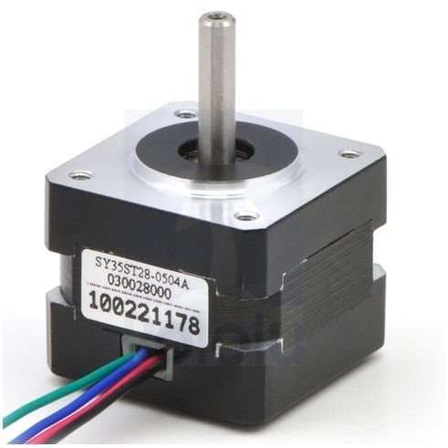
The Anatomy of a Stepper Motor
To better understand how one works, let’s start by tearing down a simple stepper motor. As you can see, these motors are built for direct drive loads containing a few key components.
- Axle – Transfers the mechanical power of the motor to the user application
- Bearings – Minimizes friction for the axle
- Magnets – Provide a magnetic field for the coils to attract and repel
- Poles – Increases the resolution of the step distance by focusing the magnetic field
- Coils – Converts electricity to a magnetic field that drives the axle
- Stator – Increases the efficiency of the coils by focusing the magnetic field
- Contacts – Brings power from the controller to the brushes
Theory of Operation
Stepper motors behave exactly the same as a brushless motor, only the step size is much smaller. The only moving part is the the rotor, which contains the magnets. Where things become complicated is orchestrating the sequence of energizing coils. The polarity of each coil is controlled by the direction of current flow. The animation demonstrates a simple pattern that controllers would follow. Alternating current changes the polarity, giving each coil a “push/pull” effect. A notable difference is how the magnet structure of a stepper is different. It is difficult to get an array of magnets to behave nicely on a small scale. It’s also very expensive. To get around this, most stepper motors utilize a stacked plate method to direct the magnetic poles into “teeth”.
In a brushless motor, back EMF is used to measure velocity. A stepper relies on the short throw of each winding to “guarantee” it reaches the desired point in time. In highspeed travel, this can lead to stalling where the rotor can’t keep up with the sequence. There are ways around this, but they rely on a higher understanding of the relationship between motor windings and inductance.
Pros
- Excellent position accuracy
- High holding torque
- High reliability
- Most steppers come in standard sizes
Cons
- Small step distance limits top speed
- It’s possible to “skip” steps with high loads
- Draws maximum current constantly
Linear Motors
The future is linear! In high-speed pick and place machines speed is everything. With speed comes friction, with friction comes maintanence, with maintanance comes downtime, with downtime comes lost productivity. By removing the components needed to transfer rotary to linear motion, the system becomes much lighter and more efficient. Linear motors are simple to maintain, and, with only one moving part, are incredibly reliable. Did I mention they are incredibly fast?! This is the pick and place machine we are using in production, and it is incredibly fast! This machine also packs such a punch, there is a warning for pacemakers on it. There is an entire row of high-power, rare-earth magnets.
The Anatomy of a Linear Motor
To better understand how one works, let’s look inside our pick and place machine downstairs.
- Motion Module – Contains electromagnets and controller.
- Magnets – Provide a magnetic field for the coils to attract and repel
- Linear Bearing – Keeps the motor in alignment with magnets and is the only moving part.
Theory of Operation
The mechanics of a linear motor is nearly identical to a brushless motor. The only difference is if you were to take a brushless motor and unfold it into a straight line you’d have a linear motor. The Motion Module is the only moving part. Where things become complicated is orchestrating the sequence of energizing coils. The polarity of each coil is controlled by the direction of current flow. The animation demonstrates a simple pattern that controllers would follow. Alternating current changes the polarity giving each coil a “push/pull” effect. In a linear motor, there is typically an encoder or some advanced positioning system to keep track of the location of the Motion Module. To reach a high position accuracy, the controllers are much more complicated than anything found on a conventional system. Microstepping is a method to “throttle” the magnets to provide smooth and precise motion. To achieve this though, linear motors require a highly specialized controller tuned for each motor. As controller technology improves, we are likely to see these motors decrease in price. Maybe someday our 3D printers will print in seconds and not hours!
Pros
- Reliable
- High speed
- Efficient
- No rotary to linear conversion required
Cons
- Expensive
- Require custom controllers
- Purpose built for each system
- Expensive
So we took a look at some different types of motors and how they might be used. Selecting a motor will require you to first determine the application requirements. With these requirements, you can look at the strengths and weaknesses of each motor type. But more importantly, look for the ratings on each motor. Each motor will have values for input power and output power. You can calulate the load requirements of a system but, sometimes it’s easy enough to just try it!