Hobby servos are small, modular actuators developed by the radio control (RC) hobby industry for remote manipulation of everything from miniature boat rudders and car steering linkages to model airplane flaps and toy parachutist release mechanisms. The RC market is large and competitive, which has led to a proliferation of servos that have been optimized for characteristics including size, speed, torque, and price. This modularity, variety, ubiquity and cost-effectiveness of servos make them attractive generic actuators for small robots and other electromechanical systems.
Servos are the actuators in the standard RC system: they take the command from the receiver, use the electrical power from the battery, and physically move. The vast majority of servos have rotary outputs that move through a bit less than 180 degrees, though there are some specialty servos with linear outputs (the output moves straight back and forth, rather than rotating) and outputs that can turn a full rotation or more. What makes a servo a servo is that it takes care of getting the output to the commanded position by monitoring the output and applying power accordingly: if you push against a servo, it will push back to try to maintain its position.
Performance Specifications
The primary performance specifications for servos are torque, speed, weight, and size:
- Torque – In many applications, torque is one of the most important considerations. Generally, larger servos offer more torque, but expensive servos that use exotic materials can offer more torque without giving up any other features. Within a given size and price, some trade-off between torque and speed is usually available. Some manufacturers might just use completely different item numbers for different performance points; others might use a base model number with suffixes like “T” or “XF” to indicate the “high-torque” and “extra-fast” versions of otherwise identical servos. Standard servos typically provide forty to a few hundred ounce-inches; giant servos can get past 500 ounce-inches, and the smallest servos provide less than ten ounce-inches.
- Speed – Servo speed is usually specified in what might seem to be an odd manner: the time required to move sixty degrees. More generally common units for speed are rotations per second or rotations per minute (RPM), but those are not so useful for a device that does not make full rotations and spends a lot of its time accelerating. (If using a time for “speed” makes you uncomfortable, think of 100-meter sprinters: we report their performance in seconds, not miles per hour.) A typical servo speed is around 0.15 seconds per 60 degrees; less than 0.1 seconds is quite fast, and more than 0.25 seconds is noticeably slow.
Weight – Weight is strongly correlated to output power (which is the product of speed and torque); going to higher speeds or higher torques (without corresponding drops in the other) will generally mean more weight. Standard servos weigh 1.5–2 ounces, giant servos can weigh five ounces or more, and micro servos weigh half an ounce or less. Small servos tend to use shorter and thinner wires to save weight. - Size – Most servos have the same general shape, and the size generally scales with the output power and weight. However, there are some servos with noticeably different aspect ratios. These tend to be designed for specialty applications such as retractable landing gear or fitting in thin wings.
There are other specifications that cover aspects like materials used in the gears and the technology of the internal motor or electronics, but I’ll leave those for another post. There are also many other parameters that robot builders might want to know but which are not specified; at least some of these missing specifications are because of the servo’s intended use.
Ramifications of the servo’s intended use
While servos are great for their intended use, they have shortcomings as general-purpose actuators. It can be frustrating that there are thousands of different servos that all have the same limitations, so before wasting time looking for a servo that doesn’t exist or denouncing a hobby store for not carrying it, it’s good to consider why some things that matter to a robot builder might not matter to the RC hobbyist.
Lack of feedback
Probably the most disappointing shortcoming of regular servos is that they provide no feedback. Since the main feature of a servo is its ability to get the output to the commanded position, it must know the output position, which could be very good information for other parts of a robot. Roboticists might want their servos to report all kind of other things, like how hard the servo is exerting itself to maintain a position or if there has been some kind of fault in the servo. Unfortunately, the basic paradigm of one-way communication from the radio control transmitter to the receiver means that even if a servo could somehow tell the receiver something, the receiver would still not be able to communicate that back to the remote operator, so there is no incentive for normal servo manufacturers to address this limitation.
Twitch on power-up
A subtle problem related to the lack of feedback is that there must be some first command that a servo receives after being turned on. Since there are no commands for limiting speed or power, if the output shaft is not already in that commanded position, the servo will instantly try with all its might to head for the position. This doesn’t really matter if it means a twitch in an airplane flap when it is turned on, but it can be quite dangerous for a robot arm or leg made of servos since trying to jerk a more massive mechanism could put a lot more stress on the servos. To limit the effects of this problem, it can be helpful to have a power-down position that the mechanism is put in before cutting power; on power-up, the first command can be to go to that position, and ideally, the mechanism will still be in that position and thereby minimize any self-destructive twitch. (Subsequent commands can move the servo slowly by sending position commands that are very close to each other, but there is no way of guaranteeing that the first command is for a position close to where the servo already is.)
Limited rotation range
The standard rotation range being too limited is probably the second most common lament I have heard. With the exception of a few specialty applications like model sailboats, most radio control model applications just don’t need more than about ±60 degrees of range. Most servos have about 150 to 200 degrees of range, so from the perspective of the manufacturers, that is more than enough for the necessary 120 degrees, and the exact limit on the range is usually not even specified. That can be quite annoying for a person who really wants a guaranteed 180 degrees.
Low operating voltage – A relatively low operating voltage is a great feature for a system intended to use a few servos wirelessly for an hour at a time or less. It’s less convenient for a hexapod walking robot or a continuously operating but stationary animatronic puppet since the low voltage means more current is needed for the same amount of power. If you want to use twenty servos at once, you need a 20-amp power supply, which is not necessarily cheap, and you need fairly thick wires to handle the current efficiently.
Short servo cable length
A requirement that servos be within a few feet of each other is not much of a limitation for a model whose largest dimension is not much more than that. It’s tempting to use servos in larger-scale projects, but the low operating voltage and the command protocol used is not appropriate for just using longer wires. If you have a project in which you want servos spaced every ten feet or more, you will likely need to have some extra electronics at each servo so that the distance from the servo to the device it is plugged into is not more than a few feet.
Current not specified
Since the currents used by servos are typically low enough, they are generally not specified. The problem is that a “low enough” stall current can add up if you have twenty servos straining at once, and a “low enough” idle current might not be low enough if you want to make a device that is powered all day but only needs to move at dawn and dusk. (This is not an indictment of servo quality: for instance, all units of one servo model might be under a manufacturer’s internal specification of 25 mA idle current; if we test one and it happens to be 5 mA and your servo is 15 mA, they are both good and close enough to zero for the intended use even though your unit is three times worse.) If you really care about your servo currents, you have to measure them yourself.
Servo connected to a mechanical speed control
Output shaft on only one side of servo
Normal servos made for the RC market have a short output shaft protruding on only one side of the case. The shaft is connected to an arm that usually pushes or pulls on some linkages, and having the shaft protrude from the other side would make the servo larger and more difficult to manufacture without much benefit for most of the intended customers. The one-sided output is not ideal for many robotics applications, and some specialty manufacturers offer brackets to enable creation of complex joints.
Not designed for backdriving
Airplane modelers aren’t really clamoring for a feature whereby they can pose their airplanes’ control surfaces and have them “learn” the positions. (This is also related to the above mentioned limitation of no feedback.) Robot designers, on the other hand, might want to externally manipulate their creations. Unfortunately, most servos are not made for that, and some servos, especially the sub-micro ones with itty bitty gears, can reliably break if you try to back drive them (even when power is not applied).
Audible noise
This might matter more to magic trick and kinetic sculpture creators than to most hobby robot builders, whose robot was never realistically going to be able to sneak up on the cat, anyway. Unfortunately for those looking for quiet servos, radio control folks using servos in models with loud engines and operating hundreds of feet away don’t really care about how loud a servo is.
Limited response or update rate
Servos are designed for real-time remote operation by humans, for which the standard update rate of fifty times per second is more than adequate. However, that might seem kind of slow for an autonomous robot which might be capable of updating its calculation of the desired servo position several hundred times per second. There are some servos, usually intended for use in conjunction with a gyro or other sensor on model aircraft, that can handle faster command rates.
Limited options for larger servos
Servo manufacturers keep introducing newer servos, but the advancements tend to be in making micro servos smaller or in improving performance in standard servos. The same is not true for giant servos. Existing giant servos are already big enough for models with twelve foot wingspans and costing thousands of dollars, so there probably is not much of a market for even bigger servos. Also, the low-voltage limitation becomes a bigger problem the bigger a servo is and the more power it needs, so really big servos need some alternative and less standardized way of being powered.
Electrical connection
Servos have three-wire cables that supply power and commands to servos. The cables are typically six to twelve inches long, with 22 gauge and thinner wires (smaller servos tend to have shorter and thinner wires). Since the connectors have become more standardized, the order of the wires has also become standardized, with the power wire in the middle flanked by ground and signal wires. However, the color schemes still vary. Common ones are:
> Black for ground, red for power, white for signal
> Brown for ground, red for power, and orange for signal
> Black for ground, red for power, blue for signal
My preference is for the first scheme since that offers the most contrast; the orange and brown of the second scheme can look kind of similar with bad lighting, as can the blue and black of the third approach. You are almost guaranteed to instantly destroy a servo if you connect power backwards, so make sure you double-check your connections.
The three-conductor cable is terminated with a 3-pin connector, which is almost universally a female connector with 0.1″ spacing. Unfortunately, much of the RC world calls this female connector a male connector. As with the cable colors, the connector colors can vary. The “Futaba” plug, has an extra polarizing tab that can be cut off to match the others, which are called “JR” and “Airtronics Z” . Some of the brand names might vary by country; the most common names I see from generic servo makers in China are “Futaba” and “JR”.
>>> Again: pay attention when plugging in your servos! <<<
Power
In general, the safest voltage on the servo is about 5v.
Rechargeable NiMH battery pack: 6.0 V, 2200 mAh, 3+2 AA cells
As I mentioned in the introduction to servos, servos are typically used in battery-powered applications. The batteries were historically four- or five-cell NiCd packs or four-cell alkaline packs, which yield nominal voltages of 4.8-6.0 V. Newer NiMH packs have the same voltages, and so servos tend to be designed for operation at those voltages but without specification of the exact operating range. A well-charged 5-cell pack can reach about 7.0 V, and a 4-cell pack can drop to about 4.0 V without being considered ridiculously discharged, so that is the range over which we can reasonably expect most servos to operate.
Going to higher voltages can destroy servos, so testing the upper boundary can be risky. On the other hand, lower voltages correspond to drained batteries that we hope would not lead to damaged servos, so you can safely test the lower end of the operating range with a variable power supply. If you do tests for the low end, keep in mind that individual units can vary and that the limit might be a function of variables such as the temperature.
The smaller, 1/3- and 2/3-AAA NiMH battery packs are great for miniature robots
Some servos, especially micro servos, are rated only for 4.8 V operation, which implies 4-cell operation with a maximum voltage of 6.0 V. As the RC industry embraced lithium-based rechargeable batteries, some servos intended for operation from one cell (3.7 V nominal) and from two cells in series (7.4 V nominal) emerged. The single-cell units are again on the micro side, and can have upper limits of around 4.5 V; the two-cell units might be marketed as high-voltage servos since the upper voltage limit is 9 V or higher. A three-cell nickel-based pack can generally replace a single-cell lithium battery, and a six-cell nickel pack can replace a two-cell lithium pack.
The current required by servos also tends to be unspecified. When we design with servos, as with most components, there are two main currents we care about: the quiescent or idle current, when the servo is not doing anything, and the maximum current, which in the case of a servo is the stall current. The quiescent current will give us an upper bound on how long a battery-powered application can run; the stall current tells us the minimum current our power supply has to be capable of delivering. The average current a servo consumes in actual operation will be somewhere between the two extremes and will depend on how active the servo is in the application.
The current a servo draws will be approximately linear with the supply voltage, so the currents drawn at 7 V will be almost double those at 4 V. It’s relatively easy to measure the quiescent current since it is low, constant, and flows in a low-strain scenario. Stall currents are more difficult to measure because actually stalling a servo is not that desirable, so we do not want to do it for a prolonged period. If you need to know the stall current, it’s safest to measure at the low end of the operating range and then extrapolate for higher supply voltages.
Since servo currents usually are not specified and we might not want to bother measuring each servo we use, it’s good to keep a few estimates in mind. A standard servo will have a stall current around one amp, a micro servo will need a few hundred milliamps, and a giant servo can draw ten amps or more. Since servos run at basically the same voltages, the only ways servos can offer more torque is to have higher gear ratios or to use more current. If two servos have similar speeds at the same voltage but one has five times the stall torque, it will likely draw five times the stall current.
The quiescent currents are tricker to estimate because they are not dominated by the motor the way stall currents are. There can be substantial variation in these idle currents since they depend on the electronics in the servo, but typically, the current should be in the few dozen to one or two hundred milliamp range. The quiescent current can also be complicated by the existence of two possible values: one for the case where the servo is trying to maintain a position but is already there and therefore doesn’t need to power the motor, and another for the case where the servo is “off” and not trying to maintain a position at all. (We’ll get to what it means for the servo to be “off” later.)
Servo control interface
Servos are controlled by pulses on the signal line that are referenced to the ground line, which is the return path both for servo power and the control signal. The pulse frequency is typically 50 Hz, but the exact frequency does not matter. The pulse width corresponds to the position of the servo, with 1.5 ms corresponding to the servo’s “neutral” point. This neutral point is not necessarily the midpoint of the servo’s maximum available range. Making the pulse shorter makes the servo go one way; making the pulse longer makes the servo go the other way. The normal pulse width range is 1.0 ms to 2.0 ms, which corresponds to an approximate mechanical range of 90 degrees (for most servos).
Let’s go over the basic signal we’re sending to the servo. The signal is a square wave, meaning there are two voltage levels between which we switch instantly (in real life, the transition has to take some amount of time, but that transition time is so short that we can approximate it as zero):
The signal alternates between zero volts and the pulse voltage, so there are only three parameters necessary to characterize the waveform:

Pulse voltage, V
Pulse width, t
Pulse period, T
Let’s consider each of these parameters:
Pulse voltage
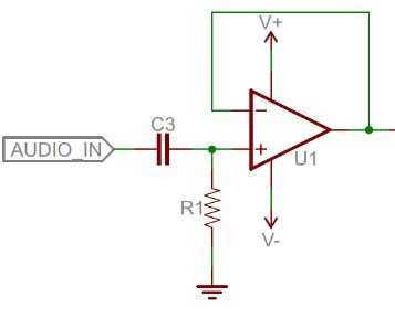
As we saw in the RC receiver output signals from last time, the pulse voltage can vary quite a bit. Modern receivers have 3.0 V signals, but many servo controllers use 5.0 V or more. For the most part, this signal amplitude does not matter too much, as a long as it is high enough for the servo to register the pulses, and the valid range is perfect for interfacing directly to a microcontroller that is running at 3.3 V or 5.0 V. We put 220-ohm resistors in line with the outputs of our servo controllers, which run on approximately 5.0 V; the resistors protect the pins in general but also prevent too much current from flowing in the event that the servo is running at a lower voltage than the signal it is getting.
Pulse width
The pulse width is generally the most important part of the interface, and that is what we intentionally vary to change the command to the servo. The general idea is simple: a pulse width of 1.5 ms is what we consider “neutral”; increasing the pulse width will make the servo go one way, and decreasing the pulse width will make the servo go the other way. However, there are a few points you should keep in mind:
The neutral point is not necessarily the middle of the servo’s absolute maximum range. For instance, a servo that is capable of 180 degrees of movement might have the output at the 100-degree point for a 1.5 ms input pulse. In that case, the available range would be 80 degrees to one side of neutral and 100 degrees to the other. The pulse width that corresponds to the middle of the available range will vary from servo to servo, even for servos that are of the same model, so if you care about getting the most range you can and having neutral mean the middle of that range, you will have to calibrate your system for each servo.
There is no standard correspondence between the pulse width and the servo position. Generally speaking, moving from 1.0 ms to 2.0 ms will yield about 90 degrees of servo movement, but that pulse width range could correspond to 100 degrees on one servo and 80 degrees on another servo. This means that any servo controller or servo control library you might use that makes any claims about absolute degrees is hiding something from you (or designed by someone who doesn’t really understand the interface). If you change servos in your design, you might have to make corresponding changes in the range of pulses you send to it, so if you are doing your own servo pulse generation, it’s a good practice to have the neutral point and range of your servo parametrized in your code. (I’ll cover more on that in a future post.)
Similarly, there is no standard minimum and maximum pulse width. If you keep making the pulses wider or narrower, servos will keep moving farther and farther from neutral until they hit their mechanical limits and possibly destroy themselves. This usually isn’t an issue with RC applications since only about half of the mechanical range is ever used, but if you want to use the full range, you have to calibrate for it and be careful to avoid crashing the servo into its limit.
The direction that a servo turns for increasing pulse widths is not standardized, either (also, it’s usually not specified). In my diagram to the right, I show the output moving clockwise as the pulse width increases, but that could easily be the other way around. We can expect the correspondence to stay consistent between different units of the same servo model, but the direction of servo travel is yet another thing you should be able to change in your design without a lot of effort so that you have the option of changing servo models.
The servo control interface is an analog interface. The signals look digital because we have square waveforms and we use digital microcontroller outputs to create them, but because what matters is the infinitely variable time that the pulse is high, the signal is analog, and any slight jitter in the pulse width will cause corresponding twitching in the servo output.
Although we can use some pulse width modulation (PWM) hardware modules in microcontrollers to generate servo control signals, and we are changing (modulating) the pulse width, it’s not good to call the signals PWM signals because that implies the relevance of the duty cycle, which is the percentage of on (high) time of the signal. As we will see next, the frequency of the pulse train does not affect the servo position if the pulse width stays the same, so changing the duty cycle does not necessarily affect the servo position. Similarly, we could keep the duty cycle constant by stretching out both t and T by the same proportional amount, and the servo position would change since the pulse width had changed.
Pulse period
The typical pulse period is around 20 ms, which corresponds to a frequency of 50 Hz. One immediate ramification of the pulse rate is that it gives you an upper bound on how quickly you can give the servo new commands. Most servos can handle substantially faster pulse rates, and some special servos are designed to support pulse frequencies of several hundred hertz. However, a more subtle dependence on the pulse frequency shows a major difference between analog and digital servos.
The servo still generally works at the lower pulse frequency, but the duty cycle (percentage of the time that it is pushing back) goes down so that its torque also goes down. As the pulse period gets even longer, the time between attempts to correct the servo position gets correspondingly longer, and at slow pulse rate like 10 Hz, the output torque has enough ripple that it is easy to feel. Shortening the pulse period has the opposite effect; at 100 Hz, the servo is pushing back almost 50% of the time even with a slight output resistance, and with a high mechanical load, the servo is pushing back almost 100% of the time.
Digital servos have an internal microcontroller that allows the servo designers much more flexibility in how servos react. A relatively high-performance digital servo, we see that the current pulses are much quicker than the control pulses; also, even with a slight output load, the peak current is past 1.5 A at only 3.5 V. At full voltage, the current peaks would be around 2.5 A, so we see that multiple servos can quickly become a very demanding load for a power supply. At a higher mechanical load, it is especially clear that the servo’s performance does not depend on the pulse frequency.