Introduction
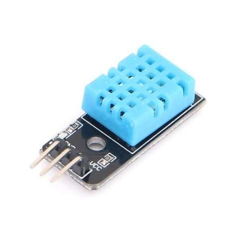
This DHT11 Temperature and Humidity Sensor features a calibrated digital signal output with the temperature and humidity sensor capability. It is integrated with a high-performance 8-bit microcontroller. Its technology ensures the high reliability and excellent long-term stability. This sensor includes a resistive element and a sensor for wet NTC temperature measuring devices. It has excellent quality, fast response, anti-interference ability and high performance.
Each DHT11 sensors features extremely accurate calibration of humidity calibration chamber. The calibration coefficients stored in the OTP program memory, internal sensors detect signals in the process, we should call these calibration coefficients. The single-wire serial interface system is integrated to become quick and easy. Small size, low power, signal transmission distance up to 20 meters, enabling a variety of applications and even the most demanding ones. The product is 4-pin single row pin package. Convenient connection, special packages can be provided according to users need.
Specification
- Supply Voltage: +5 V
- Temperature range :0-50 °C error of ± 2 °C
- Humidity :20-90% RH ± 5% RH error
- Interface: Digital
Many low cost sensors have unusual output formats, and in this case, a “Manchester-esque” output that is not SPI, I2C or 1-Wire compatible must be polled continuously. Please refer to data sheet below
Documents
- Arduino Sample Code
- DataSheet
- We have the DHT11 datasheet but its in chinese so its not easy to understand. However, the sensor protocol and timing is similar to the DHT22 so check out the DHT22 datasheet for more information
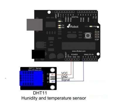
Note:- The above pin labeling have error.
Sample Code
#define DHT11_PIN 0 // define anlog port 0
byte read_dht11_dat()
{
byte i = 0;
byte result=0;
for(i=0; i< 8; i++)
{
while(!(PINC & _BV(DHT11_PIN)))
{}; // wait forever until anlog input port 0 is ‘1’ (NOTICE: PINC reads all the analog input ports
//and _BV(X) is the macro operation which pull up positon ‘X’to ‘1’ and the rest positions to ‘0’. it is equivalent to 1< delayMicroseconds(30);
if(PINC & _BV(DHT11_PIN)) //if analog input port 0 is still ‘1’ after 30 us
result |=(1<<(7-i)); //this position is 1
while((PINC & _BV(DHT11_PIN))); // wait ‘1’ finish
}
return result;
}
void setup()
{
DDRC |= _BV(DHT11_PIN); //let analog port 0 be output port
PORTC |= _BV(DHT11_PIN); //let the initial value of this port be ‘1’
Serial.begin(9600);
Serial.println(“Ready”);
}
void loop()
{
byte dht11_dat[5];
byte dht11_in;
byte i;// start condition
PORTC &= ~_BV(DHT11_PIN); // 1. pull-down i/o pin for 18ms
delay(18);
PORTC |= _BV(DHT11_PIN); // 2. pull-up i/o pin for 40us
delayMicroseconds(1);
DDRC &= ~_BV(DHT11_PIN); //let analog port 0 be input port
delayMicroseconds(40);
dht11_in = PINC & _BV(DHT11_PIN); // read only the input port 0
if(dht11_in)
{
Serial.println(“dht11 start condition 1 not met”); // wait for DHT response signal: LOW
delay(1000);
return;
}
delayMicroseconds(80);
dht11_in = PINC & _BV(DHT11_PIN); //
if(!dht11_in)
{
Serial.println(“dht11 start condition 2 not met”); //wair for second response signal:HIGH
return;
}
delayMicroseconds(80);// now ready for data reception
for (i=0; i<5; i++)
{ dht11_dat[i] = read_dht11_dat();} //recieved 40 bits data. Details are described in datasheet
DDRC |= _BV(DHT11_PIN); //let analog port 0 be output port after all the data have been received
PORTC |= _BV(DHT11_PIN); //let the value of this port be ‘1’ after all the data have been received
byte dht11_check_sum = dht11_dat[0]+dht11_dat[1]+dht11_dat[2]+dht11_dat[3];// check check_sum
if(dht11_dat[4]!= dht11_check_sum)
{
Serial.println(“DHT11 checksum error”);
}
Serial.print(“Current humdity = “);
Serial.print(dht11_dat[0], DEC);
Serial.print(“.”);
Serial.print(dht11_dat[1], DEC);
Serial.print(“% “);
Serial.print(“temperature = “);
Serial.print(dht11_dat[2], DEC);
Serial.print(“.”);
Serial.print(dht11_dat[3], DEC);
Serial.println(“C “);
delay(2000); //fresh time
}
This code contributed by:Camel
#define dht11_pin 14 //Analog port 0 on Arduino Uno
//#define dht11_pin 54 //Analog port 0 on Arduino Mega2560
byte read_dht11_dat()
{
byte i = 0;
byte result=0;
for(i=0; i< 8; i++)
{
while (!digitalRead(dht11_pin));
delayMicroseconds(30);
if (digitalRead(dht11_pin) != 0 )
bitSet(result, 7-i);
while (digitalRead(dht11_pin));
}
return result;
}
void setup()
{
pinMode(dht11_pin, OUTPUT);
digitalWrite(dht11_pin, HIGH);
Serial.begin(9600);
Serial.println(“Ready”);
}
void loop()
{
byte dht11_dat[5];
byte dht11_in;
byte i;// start condition
digitalWrite(dht11_pin, LOW);
delay(18);
digitalWrite(dht11_pin, HIGH);
delayMicroseconds(1);
pinMode(dht11_pin, INPUT);
delayMicroseconds(40);
if (digitalRead(dht11_pin))
{
Serial.println(“dht11 start condition 1 not met”); // wait for DHT response signal: LOW
delay(1000);
return;
}
delayMicroseconds(80);
if (!digitalRead(dht11_pin))
{
Serial.println(“dht11 start condition 2 not met”); //wair for second response signal:HIGH
return;
}
delayMicroseconds(80);// now ready for data reception
for (i=0; i<5; i++)
{ dht11_dat[i] = read_dht11_dat();} //recieved 40 bits data. Details are described in datasheet
pinMode(dht11_pin, OUTPUT);
digitalWrite(dht11_pin, HIGH);
byte dht11_check_sum = dht11_dat[0]+dht11_dat[2];// check check_sum
if(dht11_dat[4]!= dht11_check_sum)
{
Serial.println(“DHT11 checksum error”);
}
Serial.print(“Current humdity = “);
Serial.print(dht11_dat[0], DEC);
Serial.print(“% “);
Serial.print(“temperature = “);
Serial.print(dht11_dat[2], DEC);
Serial.println(“C “);
delay(2000); //fresh time
}

