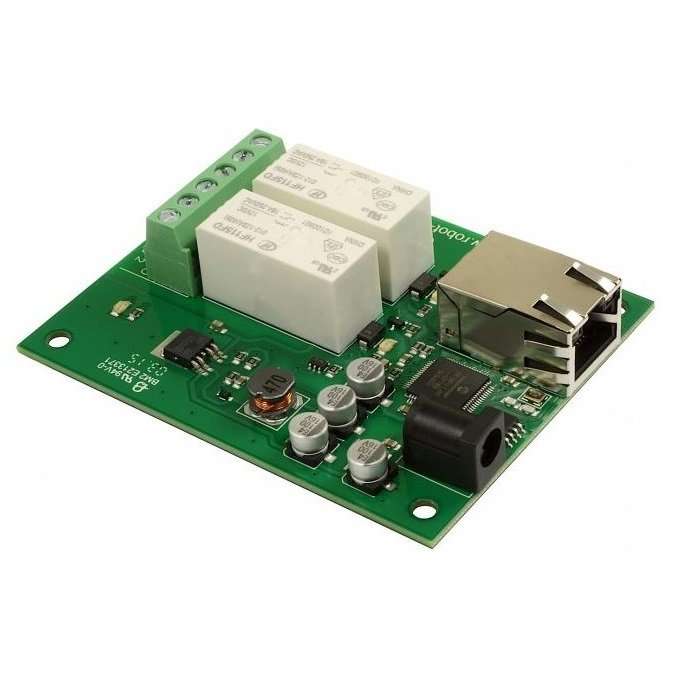
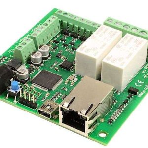
Controlled from over Ethernet using simple TCP/IP commands.
Features
Relays – 2
Power – 12V DC adaptor, supplied separately
Configuration & Test interface – HTTP (webpage)
Control interface – TCP/IP over Ethernet
Relay current – Up to 16Amp @24vdc or 250vac
Connections – Screw Terminals for N/O N/C and Common contacts
Ethernet connection – 100mb full duplex
The ETH002-B is the upgraded successor to the ETH002, we have added MQTT with optional TLS encryption. Hostname is now configurable and there is full backward compatibility to the ETH002.
Android & iPhone Apps
We have a free app IO network available for Android and iPhone to remotely control your relays, download from Google Play or iTunes. Search for “Devantech” and you will find the app.
Overview
The ETH002 provides two volt free contact relay outputs with a current rating of up to 16Amp each. The module is powered from a 12vdc supply which can be regulated or unregulated. The DC input jack is 2.1mm with positive core polarity, DC supplies are required to supply at least 500mA at 12vdc. The relays are SPCO (Single Pole Change Over) types. The normally open, normally closed and common pins are all available on the screw terminals. The ETH002 is fully compatible with the ETH-RLY02 and includes the legacy ETH-RLY02 command set.
The ETH002 has additional features over the ETH-RLY02:
1. Full Factory Reset, all ETH002 firmware and settings can be reset to the original state.
2. Firmware updates, firmware in the ETH002 is fully updateable by re-flashing the board with our custom windows program. This will be made available in the event of feature updates.
3. New Command Format, the new command format allows for consistent compatibility with future boards. New commands now allow for pulsed control of relays from 100mS to 25.5 seconds.
4. TCP/IP Password Protection, it is now possible to set a password for TCP/IP protection. This is independent of the configuration password.
Operating Temperature
-40C to +70C
LED Indication
The ETH002 provides a red LED mounted immediately next to each relay to indicate whether it is in a powered state (LED on), there is also two LED’s mounted in the Ethernet connector which will flash with Ethernet traffic. Finally there is green power LED just above the processor.
Relay Power Rating
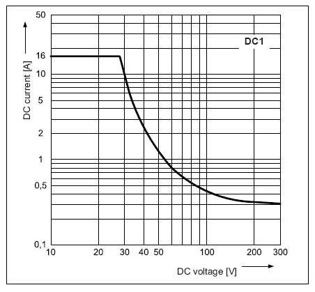
If the contact load voltage and current of the relay are in the region enclosed by the solid and dotted lines in the figure below, the relay can perform stable switching operation. If the relay is used at a voltage or current exceeding this region, the life of the contacts may be significantly shortened.
| load type | Typical applications | Rating | Max DC load capacity
|
| AC1 | Non inductive or slightly inductive loads |
16A @ 250V AC | |
| AC15 | Control of electromagnetic load (>72VA) |
3A @ 120V AC 1.5A @ 240V AC |
|
| AC3 | Control of motor | 750W | |
| DC1 | Non inductive or slightly inductive loads |
16A @ 24V DC | |
| DC13 | Control of electromagnetic loads |
0.22A @ 120V DC 0.1A @ 250V DC |
A full datasheet for the relays used on the ETH002 is here: HF115FD datasheet
First Test
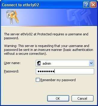
Having plugged in your 12vdc power supply and Ethernet connection, start up your web browser and type http://eth002 into the address bar, please note this only works in windows. You will be prompted for a password as shown below:
|
|
The default login is:
(The ability to change these |
You should now see the following web page:
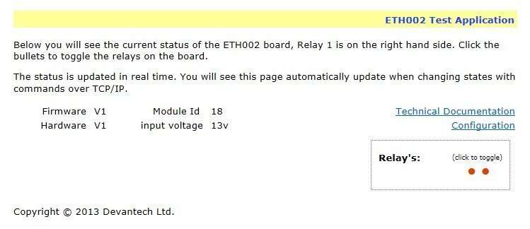
This web page will allow you to switch the relays on and off by clicking the relay buttons (the red/gray circles). It also contains a link to this technical documentation page.
Configuration
By clicking the configuration link it’s possible to configure the ETH002 IP address and subnet mask together with the ability to set a password for entry to control screens. The ETH002 now also offers the option to set a password that will be required to change any of the relay states using TCP IP commands, this is explained in the TCP/IP password section.
All settings are saved to memory so be careful to remember the username and password! Default password settings are shown in the picture below.
Version 2 now offers a latched outputs option, this will automatically save any permanent output changes (not pulsed) and restore them following power loss.
| Command |
Action |
|
| dec | hex | |
| 90 | 5A | Get software version – returns a single byte, the software version number |
| 91 | 5B |
Get relay states – sends a single byte back to the controller, bit high meaning the corresponding relay is powered |
| 92 | 5C | Set relay states – the next single byte will set all relays states, All on = 255 (11111111) All off = 0 |
| 93 | 5D | Get DC input voltage – returns relay supply voltage as byte, 125 being 12.5V DC |
| 100 | 64 | All relays on |
| 101 | 65 | Turn relay 1 on |
| 102 | 66 | Turn relay 2 on |
| 110 | 6E | All relays off |
| 111 | 6F | Turn relay 1 off |
| 112 | 70 | Turn relay 2 off |
| 119 | 77 | Get MAC Address. Returns the unique 6 byte MAC address of the module. |
We also have a free Android App available to remotely control your relays.
Java network scanner app, easily find your module even on another subnet – Devantech module finder
Examples:
Java – command line application for controlling the module
Perl – Simple example of setting an output active/inactive by tcp
PHP script – Simple example of setting an output active/inactive by tcp
Python V2 – command line application for controlling the module
Python V3 – command line application for controlling the module
Visual C# – source code for simple program, includes UDP scan to determine any boards connected to the local network
Visual Basic – source code for simple program, includes UDP scan to determine any boards connected to the local network

