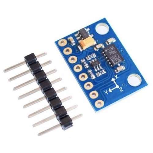
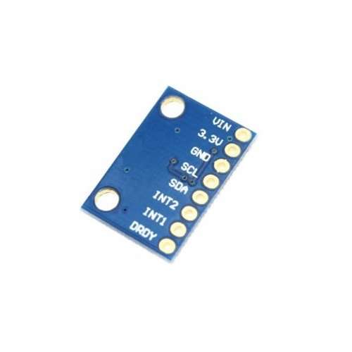
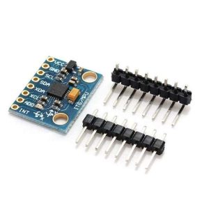
This board is a compact breakout board for LSM303DLHC 3-axis accelerometer and 3-axis magnetometer. A minimum of four connections are necessary: VIN, GND, SCL, and SDA. VIN should be connected to a 3 V to 5 V source, GND to 0 volts, and SCL and SDA should be connected to an I²C bus operating at the same logic level as VIN.
Specifications
-
Operating voltage: 3 to 5 V
-
Supply current: 10 mA
-
Output format (I²C):
-
Accelerometer: one 12-bit reading (left-justified) per axis
-
Magnetometer: one 12-bit reading (right-justified) per axis
-
Sensitivity range (configurable):
-
Accelerometer: ±2, ±4, ±8, or ±16 g
-
Magnetometer: ±1.3, ±1.9, ±2.5, ±4.0, ±4.7, ±5.6, or ±8.1 gauss
-
VIN
This is the main 3 – 5 V power supply connection. The SCL and SDA level shifters pull the I²C bus high bits up to this level.
GND
The ground (0V) connection for your power supply. Your I²C control source must also share a common ground with this board.
SCL
Level-shifted I²C clock line:
- HIGH is VIN
- LOW is 0V
SDA
Level-shifted I²C data line:
- HIGH is VIN
- LOW is 0V
DRDY
Magnetometer data ready indicator, a 3.3V-logic-level output.
- HIGH (3.3V) indicates magnetometer data can be read.
- LOW (0V) indicates the magnetometer is writing new data to the data registers. This output is not level-shifted.
INT1
Inertial interrupt 1, a 3.3V-logic-level output. This output is not level-shifted.
INT2
Inertial interrupt 2, a 3.3V-logic-level output. This output is not level-shifted.
References
If using with an Arduino, use the Arduino library to get you started. Simply download our library and connect the SCL pin to your Arduino’s I2C clock pin, and SDA pin to your Arduino’s I2C data pin and upload our test program to read out accelerometer and magnetic field data. You can reference this tutorial.

