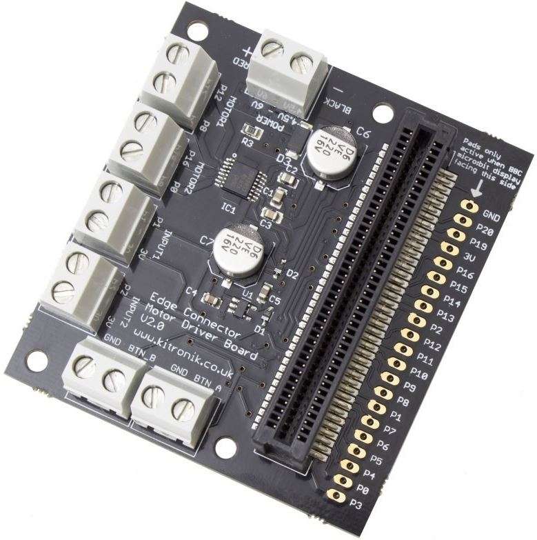
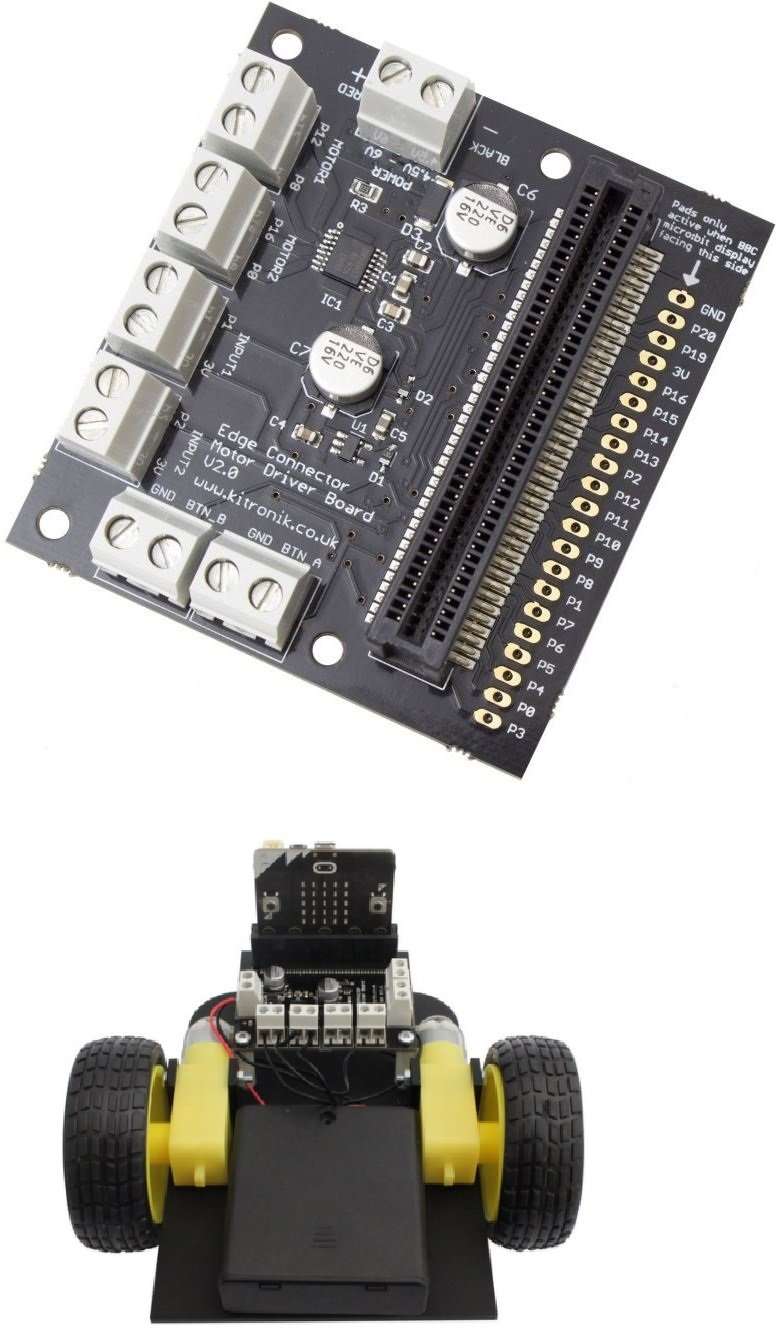
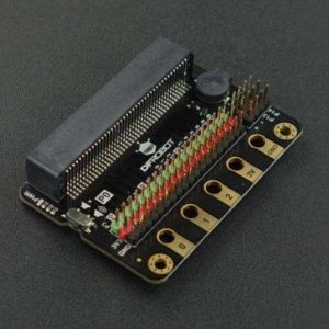
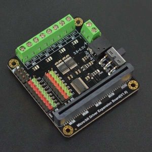
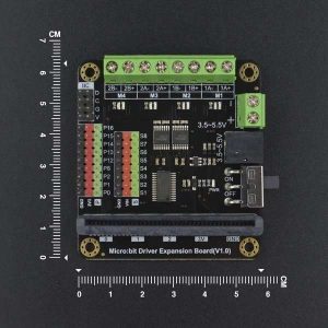
This board provides a simple way to add motor driving capability to a BBC micro:bit. It allows two motors to be driven with full forward, reverse & stop control. It has terminal blocks to connect four input devices and a regulated 3V supply is fed in to the 80 way connector to power the inserted BBC micro:bit.
In this new version, the pins from the BBC micro:bit are now broken out to pads on the end of the Motor Driver Board. These pads can either be soldered onto directly, or they are the correct spacing for our PCB pin headers.
Technical Data:
-
Operating Voltage (Vcc) – 4.5V to 6V.
-
Number of motor channels – 2 (2 motors with forward + reverse control, controlled by P0, P8, P12 & P16).
-
Typical motor output Voltage (Vm) @ 1.5A output per channel – Vm = Vcc 0.3V.
-
Max Current per motor channel – 1.5A.
-
Digital only inputs – 2 (button A / B).
-
Digital or analog input / output pins (P1 & P2) – 2 (P1 & P2).
-
Digital output drive current – 5mA.
It includes an integrated Edge Connector slot for your BBC micro:bit to easily slot into. It also features external connections to the Buttons A and B inputs. This allows additional switches to be connected to the motor driver board and the state of these can then be read by the BBC micro:bit.
Get up to speed quickly. Example Microsoft TouchDevelop code and example connections in the datasheet (below).
Features:
Drive 2 motors with full forward, reverse and stop control.
Terminal blocks for easy connection of motors and inputs.
4 inputs (2 analogue inputs and 2 provide external connections to Buttons A and B as inputs).
Includes Edge Connector for the BBC micro:bit to slot into.
Provide regulated power to the BBC micro:bit.
Access the other BBC micro:bit pins easily and conveniently.
Contents:
1 x Edge Connector Motor Driver Board for the BBC micro:bit – V2.
Dimensions:
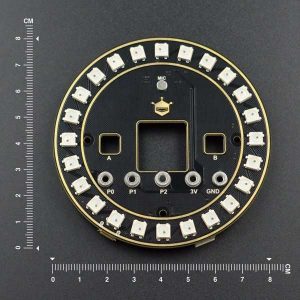
Length: 67mm.
Width: 61mm.
Height: 18mm.
Video HERE
Requires:
1 x BBC micro:bit.
4.5 – 6V Power Supply.
2 x DC Motors (that are compatible with the power supply used).
1 x Flat-headed Terminal Screwdriver.
Resources:
Kitronik Custom Motor Driver PXT Editor Blocks (Use this URL to add them to the PXT Editor).
Click here to download the datasheet.
Using PWM with the Kitronik Motor Driver Board
Way back when we first released our Motor Driver Board the microbit Block Editor only allowed digital write on the pins we used for controlling motors. This meant that motors had to be full on or off. Thanks to an update in the PXT editor you can now use PWM to control the motors and therefore the speed of your buggy.
Robot Buggy Part 2 The Line Following Buggy
The line following buggy for the BBC micro:bit is a great kit for students to build as it combines several elements of design and technology; electronics, mechanical assembly and coding and it is this buggy that the Robot Buggies are built upon. The kit has relatively few parts and is simple to build, making it a suitable option as a classroom activity.

