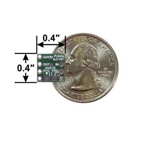
Dimensions
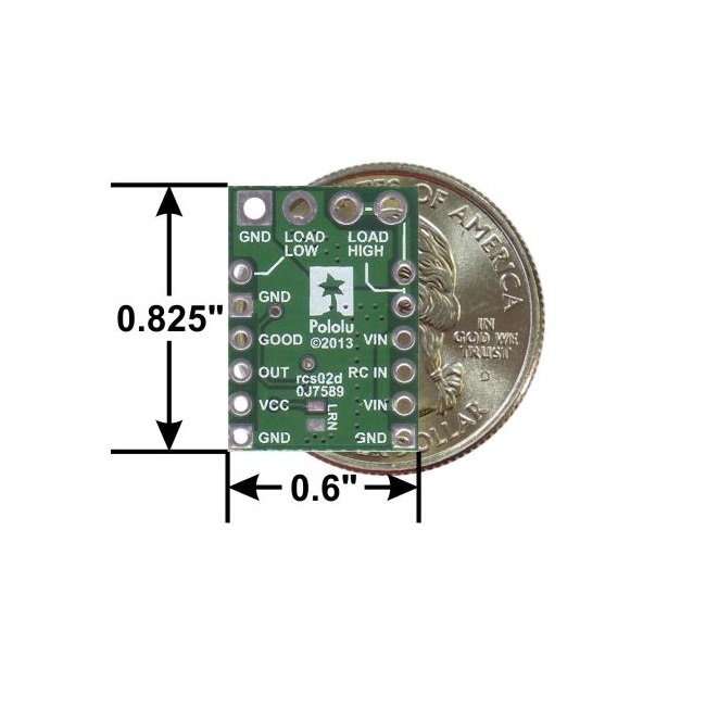
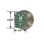
| Size: | 0.6″ × 0.825″ |
|---|---|
| Weight: | 1.2 g [1] |
General specifications
| Minimum operating voltage: | 2.5 V |
|---|---|
| Maximum operating voltage: | 16 V [2] |
| Maximum output current: | 15 A |
Notes
1 – Without included optional headers and terminal block.
2 – For the RC switch module. The load supply voltage should not exceed 30 V.
Overview
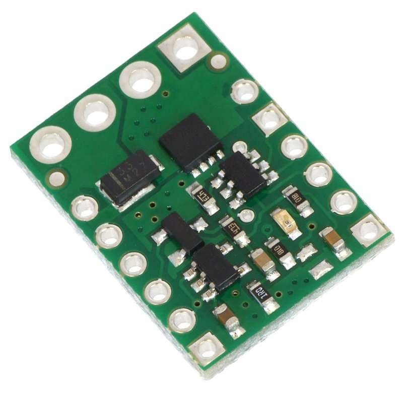
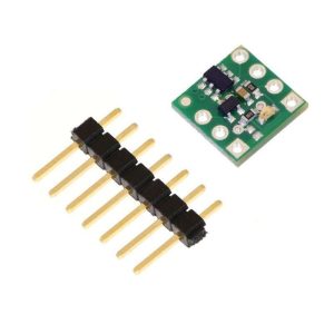
The Pololu RC switch with medium low-side MOSFET can be used with standard hobby radio control systems for radio control switch applications or simple interface applications. Example uses include converting extra RC receiver or servo controller outputs to simple high/low signals that can control LEDs or relays and connecting RC systems to microcontroller projects that do not have the necessary resources for decoding the RC interface. Two outputs indicate the presence of a valid signal and whether the switch is on or off, and an integrated low-side MOSFET turns on when the switch is on, allowing the board to drive moderate loads directly. The switch also features a flyback (or freewheeling) diode across the load outputs so that you can connect a coil to them, such as a motor or relay, without any additional external components.
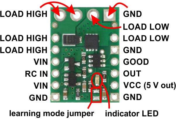
An onboard regulator allows the switch to be powered from voltages between 2.5 V and 16 V. This allows the board to be powered from a 4- or 5-cell NiMH or NiCD battery pack. The battery pack will typically be connected to an RC receiver or servo controller, which passes the power on to the RC switch. The board’s MOSFET can deliver up to 15 A with VCC at 5 V and can handle load supply voltages up to 30 V.
The RC switch measures the width of incoming RC pulses and compares it to a user-configurable threshold (with ±64 µs of hysteresis) to decide whether to turn on the MOSFET. By default, the threshold is approximately 1700 μs, with switch activation occurring above the threshold (longer pulses), but the switch has a learning mode that allows you to change the threshold and the activation direction. A safe-start feature reduces the likelihood of unexpected activation.
This compact unit measures 0.6″ × 0.825″ and weighs just over a gram (0.04 oz) without the included header pins.
Outputs and indicator LED
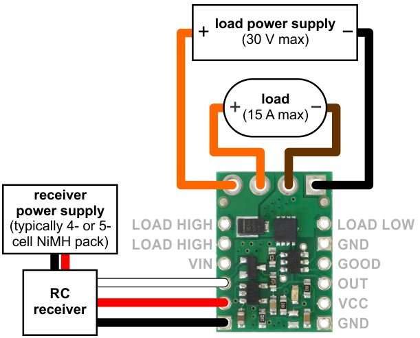
The RC switch provides feedback about what state it is in via a yellow indicator LED. Status information is also provided on two output pins:
- The GOOD pin indicates the presence of a valid RC signal (10–330 Hz pulse rate, 0.5–2.5 ms pulse width).
- The OUT pin indicates whether the MOSFET is on.
More information about using the Pololu RC switch with medium low-side MOSFET can be found in the user’s guide.
Included hardware
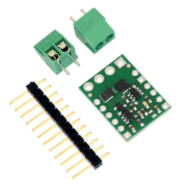
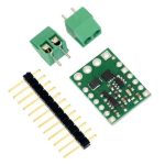
A 12-pin 0.1″ straight breakaway male header and two 3.5mm 2-pin terminal blocks are included with the Pololu RC switch with medium low-side MOSFET. The header pins can be used to connect the RC switch to perfboards or breadboards. Please note that the included terminal blocks are only rated for 10 A; for higher power applications, use thick wires soldered directly to the board.

