Note: The QTR-3RC reflectance sensor array requires digital I/O lines to take readings. The similar QTR-3A reflectance sensor array is available with analog outputs.
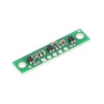
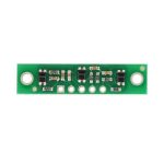
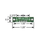
This compact module packs three IR LED/phototransistor pairs onto a 1.25″ × 0.3″ board. The sensors are mounted on a 0.375″ pitch, allowing this array to be used as a minimal detector for a line-following robot. Each sensor provides a separate digital I/O-measurable voltage output.
Functional Description
The QTR-3RC reflectance sensor array is intended as a line sensor, but it can be used as a general-purpose proximity or reflectance sensor. The module is a convenient carrier for three IR emitter and receiver (phototransistor) pairs. With sensors spaced at intervals of 0.375″ (9.525 mm) along of the board’s longer axis, this array works well as a minimal detector for line-following robots, as line-following courses are commonly made using 3/4″ (19 mm) black electrical tape. The middle sensor is slightly offset along the short axis of the board.
Each phototransistor uses a capacitor discharge circuit that allows a digital I/O line on a microcontroller to take an analog reading of reflected IR by measuring the discharge time of the capacitor. Shorter capacitor discharge time is an indication of greater reflection.
The LED current-limiting resistors are set to deliver approximately 17 mA to the LEDs when VCC is 5 V, making the total board consumption just over 50 mA. The schematic diagram of the module is shown below:
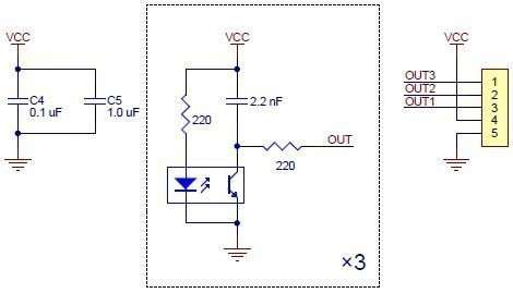
This schematic is also available as a downloadable pdf.
Specifications

- Dimensions: 1.25″ × 0.3″ × 0.1″ (32 mm × 8 mm × 3 mm) (without header pins installed)
- Operating voltage: 5.0 V
- Supply current: 50 mA
- Output format: 3 digital pulse signals
- Optimal sensing distance: 0.125″ (3 mm)
- Maximum recommended sensing distance: 0.25″ (6 mm)
- Weight without header pins: 0.02 oz (0.6 g)
Interfacing the QTR-3RC Outputs to Digital I/O Lines
Like the Parallax QTI, the QTR-3RC module has three identical sensor outputs that require a digital I/O line capable of first charging the output capacitor (by driving the line high) and then measuring the time for the capacitor to discharge through the phototransistor. This measurement approach has several advantages:
- No analog-to-digital converter (ADC) is required
- Improved sensitivity over voltage-divider analog output
- Parallel reading of all three sensors is possible with most microcontrollers
The typical sequence for reading a sensor is:
- Set the I/O line to an output and drive it high
- Wait several microseconds to give the 2.2 nF capacitor node time to reach 5 V
- Make the I/O line an input (high impedance)
- Measure the time for the capacitor node to discharge by waiting for the I/O line to go low
These steps can typically be executed in parallel on multiple I/O lines.
With a strong reflectance, the discharge time can be as low as several dozen microseconds; with no reflectance, the discharge time can be up to a few milliseconds. The exact time of the discharge depends on your microcontroller’s I/O line characteristics. Meaningful results can be available within 1 ms in typical cases (i.e. when not trying to measure subtle differences in low-reflectance scenarios), allowing up to 1 kHz sampling of all three sensors.
Our Pololu AVR library provides functions that make it easy to use these sensors with controllers. Please see the QTR Reflectance Sensors section of our library command reference for more information. We also have a Arduino library for these sensors.
Included Components
This module has two mounting holes intended for #2 screws (not included); if the mounting holes are not needed, the ends of the PCB can be ground off to make the unit even smaller (less than 1″ wide). The reflectance sensor array ships with a 1×5 straight male header stripand a1×5 right-angle male header strip as shown below. You can also solder wires, such as ribbon cable, directly to the pads for the smallest installation.
Documentation and other information
Pololu QTR Reflectance Sensor Application Note
> Information about using the Pololu QTR-xA and QTR-xRC reflectance sensors, including sample oscilloscope screen captures of sensor outputs.
Pololu AVR C/C++ Library User’s Guide
> Information about installing and using the C/C++ libraries provided for use with Pololu products.
Arduino Library for the Pololu QTR Reflectance Sensors
> This guide explains how to use the QTRSensors library to read Pololu QTR sensors and QTR sensor arrays with the Arduino.
Pololu AVR Library Command Reference
> A reference to commands provided in the Pololu C/C++ and Arduino libraries for the AVR.
Building Line Following and Line Maze Courses
> Step-by-step instructions for building your own line-following courses.
File downloads
- QTR-3RC reflectance sensor array schematic diagram
- Printable schematic diagram for the QTR-3RC reflectance sensor array.
- Datasheet for the Sharp GP2S60 compact reflective photointerrupter
- Datasheet for the sensor used on the QTR-3RC and QTR-3A Reflectance Sensor Arrays and on the Optical Encoders for micro metal gearmotors.