Perfect for Animatronics
All 84 channels can be your choice of Logic input, Logic output, or Servo output, Additionally 36 of the channels can be analogue inputs with 10-bit resolution. A PC application, with full source code, is freely available to allow you to quickly evaluate the SD84’s capabilities.
Servo Channels – Up to 84
Logic Outputs – Up to 84
Logic Inputs – Up to 84
10-bit Analogue Inputs – Up to 36
Servo Refresh Rate – 20mS under all conditions
Position Control – Directly programmed in uS
Speed Control – From maximum down to 20 seconds for full rotation
Servo Power – Separate terminals for voltage of your choice in groups of 8 servo’s
Logic Power – Direct from the USB Bus
Control interface – USB
Overview
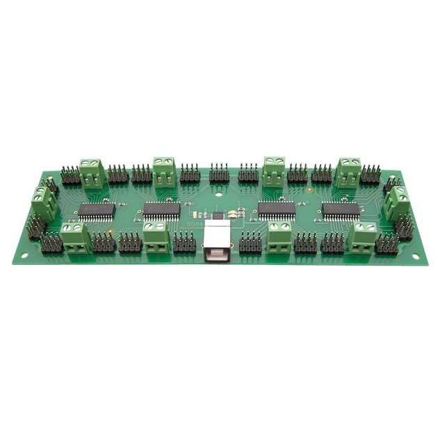
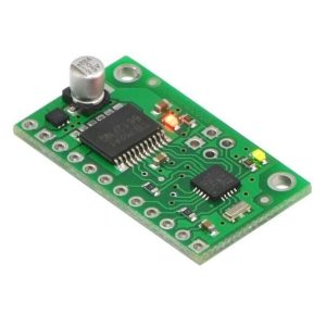
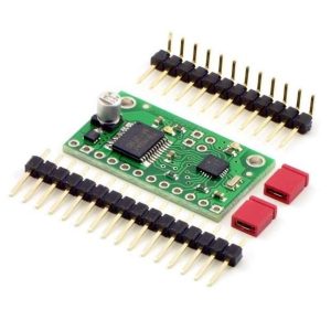
The SD84 is an 84 channel servo controller module. It will drive up to 84 RC servo’s and maintain a 20mS refresh rate, regardless of the number of servo’s used or their positions (pulse widths). It controls both the speed and position of the servo’s. It’s controlled by sending commands to the on-board processors over the USB bus. Each of the 84 channels can be a Digital Input, Digital Output or Servo Output. Additionally, 36 of the channels can be 10-bit Analogue inputs, making this a great animatronics controller.
Features
- Up to 84 channels of digital inputs.
- Up to 84 channels of digital outputs.
- Up to 84 channels of servo outputs.
- Up to 36 channels of 10-bit analogue inputs.
- Controlled and Powered from the USB bus.
- Drivers available for Windows, Apple, Linux and Open BSD.
Connections
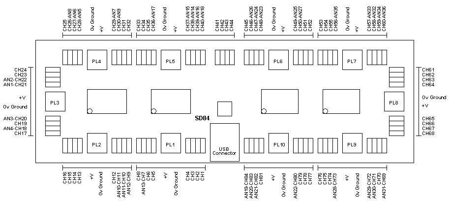
The SD84 has 84 sets of 3-pin headers, in groups of 4 at a time. In all cases, the pin nearest the outside of the PCB is 0v Ground. The middle pin is +V power for the servo from the associated 2-pin screw terminals. The inside pin, nearest the CPU’s is the signal pin.
Power
The logic circuitry on the SD84 module is powered from the USB bus and does not require any external power. You need to provide external power for the servo’s or any other circuitry you want to connect to the I/O’s. The servo’s are powered in groups of 8 servo’s. PL1 provides the power for servo’s 1 to 8 on ch1 to ch8. The only exception is PL5 which powers 12 servo’s ch33 to ch44 inclusive. The bar lines on the diagram above indicate which servo’s are powered from which screw terminals. Each group can be powered from a different voltage, but note that the 0v grounds are all common and connected together on the PCB.
Connecting Servo(s)
The servo’s are plugged directly onto the SD84, with the ground pin (black wire on a hitec servo) nearest the outside of the PCB.
First Step – Get The Drivers
The SD84 module uses the FTDI FT232R USB chip to handle all the USB protocols. The documentation provided by FTDI is very complete, and is not duplicated here. Before using the SD84, you will need to install FTDI’s Virtual COM Port ( VCP ) Drivers. These drivers appear to the system as an extra Com Port ( in addition to any existing hardware Com Ports ). Application software accesses the USB device in the same way as it would access a standard Windows Com Port using the Windows VCOMM API calls or by using a Com Port Library. Drivers are available for Windows, Apple, Linux and Open BSD systems directly from the FTDI website. You should get and install the drivers now, before you connect the SD84 to your computer. The Drivers page is here.
Which COM port?
After installing the drivers, and plugging in the SD84 module to a spare USB port, you will want to know which COM port it has been assigned to. This will vary from system to system depending on how many COM ports you currently have installed. To find out where it is with Windows98, right click on your “My Computer” desktop icon and select the “Device Manager” tab. Now scroll down and open the “Ports (COM & LPT)” tab. You should see the USB serial port listed – COM2 in the example below. If you want to change the COM port number – just right click on it, select properties, select advanced and select the COM port number from the available list. With Windows XP, select “Start”, then right click “My computer”, then select “Properties”, then the “Device Manager” tab.
The COM port should be set up for 115200 baud, 8 data bits, no parity and two stop bits.
With the drivers installed you can now connect the SD84 and Windows will register the drivers.
Internal Registers
There are three internal registers associated with each of the 84 channels.
- A “Mode” register (1 Byte) that defines the current mode of the channel, INPUT, OUTPUT_LOW, OUTPUT_HIGH, SERVO or ANALOGUE.
- A “Servo” register (2 Bytes) that defines the position of the servo in uS. The “Servo” register is an integer (two bytes). The speed and low byte/high byte of the position.
- A “Speed” register (1 Byte) that defines the speed that the servo’s change position.
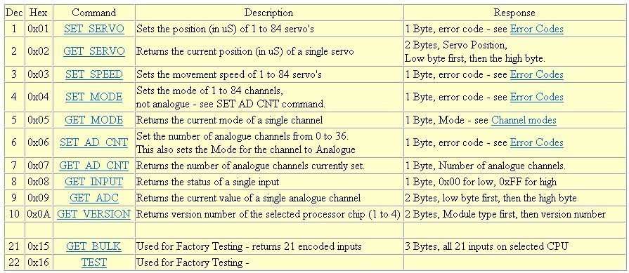
Commands
Full SD84 Documentation

