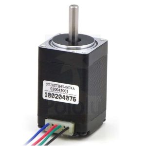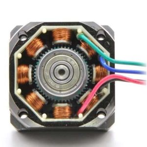
This Stepper motor can be used in accurate control. You can control this motor easily by using ULN2003 Stepper Motor Driver.
Specification
- Diameter: 28mm
- Voltage: 5V
- Step angle: 5.625 x 1 / 64
- Reduction ratio: 1 / 64
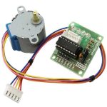
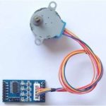
ULN2003 Stepper Motor Driver Board uses the ULN2003 DARLINGTON ARRAYS to drive the 4-phase 5-wire stepper motor (5v-12v). It’s easy to use Arduino or other development platform to drive the stepper motor by this diver board. The Mini Stepper Driver is small size and easy to use. It used ULN2003 to amplify the control signal from the Arduino. The Drive voltage can be up to 15v.
Features
The most easy module to learn how to control the Stepper and finish the simple project.
- The logic control voltage: 3~5.5V
- Motor Supply Voltage: 5~ 15V
- It can sink 500mA from a 50V supply,but you’d better limit the driver voltage under 15v.
- Operating temperature: -25 degree Celsius ~ +90 degree Celsius
HOW TO CONTROL STEPPER
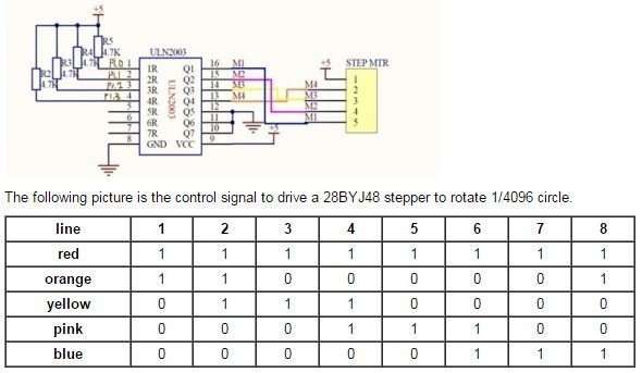
Step motor motion is enabled by converting pulse to angle displacement. So if you give stepper driver a certain pulse signal, it will drive step motor to a certain angle. you can control the angle the stepper moved by the number of the pulse. And you also can control the speed of the stepper rotate by the frequency of the pulse. The following picture is the schematic of the stepper driver.
So we defined the time series in a array:
byte CCW[8] = {0x09,0x01,0x03,0x02,0x06,0x04,0x0c,0x08};//CouterClockWise

byte CW[8]= {0x08,0x0c,0x04,0x06,0x02,0x03,0x01,0x09}; //ClockWise
and in the following usage it will run, and then you must know how to drive a stepper.
Usage
-
Stepper Control
This usage is to drive a 28BYJ stepper. The stepper stopped when pushed the stop_button. It also can be changed to control the stepper to counterclockwise or clockwise rotate. Connect 28BYJ step motor to mini stepper driver as below:
Sample sketch
/***************************
This code is used to control 28BYJ stepper
it can be changed to control almost all the 4-wire or 5-wire stepper.
*************************/

/*
The time Series to control the stepper
--make your making more easy!
*/
byte CCW[8] = {0x09,0x01,0x03,0x02,0x06,0x04,0x0c,0x08};
byte CW[8] = {0x08,0x0c,0x04,0x06,0x02,0x03,0x01,0x09};

const int stop_key = 14;  //stop_button connect to Arduino-A0
byte  change_angle=64;  //change the parameter to change the angle of the stepper

void Motor_CCW()    //the steper move 360/64 angle at CouterClockwise
{
for(int i = 0; i < 8; i++)

for(int j = 0; j < 8; j++)
{
if(digitalRead(stop_key)==0)
{
PORTB =0xf0;
break;
}
PORTB = CCW[j];
delayMicroseconds(1150);
}
}
void Motor_CW()  //the steper move 360/64 angle at Clockwise
{
for(int i = 0; i < 8; i++)

for(int j = 0; j < 8; j++)
{
if(digitalRead(stop_key)==0)
{
PORTB =0xf0;
break;
}
PORTB = CW[j];
delayMicroseconds(1150);
}
}

void setup()
{
pinMode(stop_key,INPUT);
digitalWrite(stop_key,HIGH);
Serial.begin(57600);
DDRB=0xff;
PORTB = 0xf0;
for(int k=0;k  {
Motor_CCW();
}
}

void loop()
{
Motor_CCW();  //make the stepper to anticlockwise rotate
// Motor_LR(); //make the stepper to clockwise rotate
}
***The connected stepper would rotate with a changing direction for this progam.