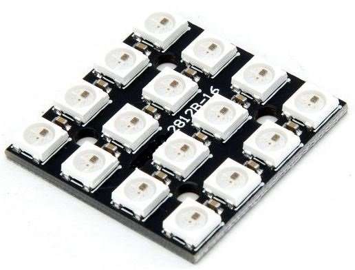
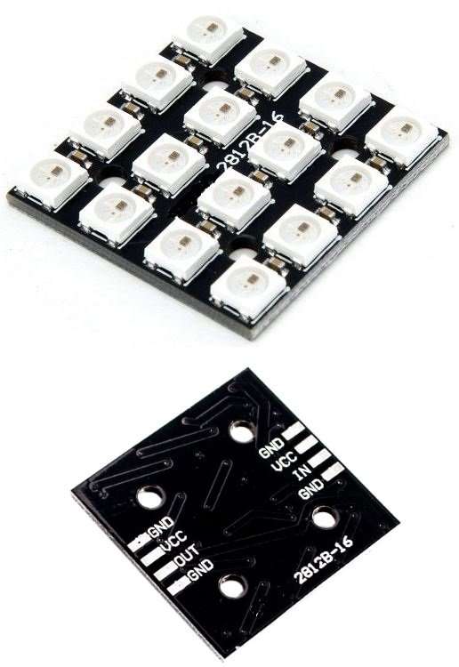
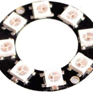
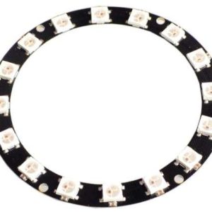
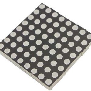
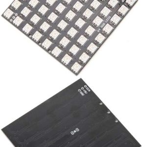
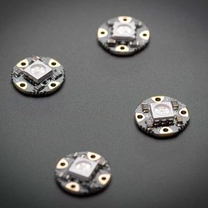
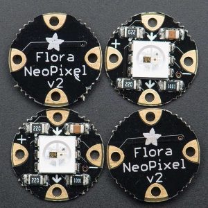
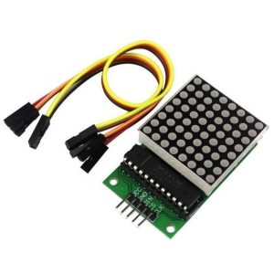
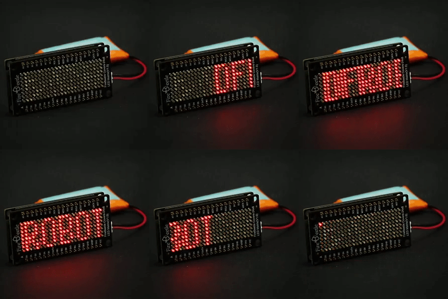
Arranged in an 8×8 matrix, each pixel is individually addressable. Only one microcontroller pin is required to control all the LEDs, and you get 24 bit color for each LED.
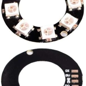
Wiring it up is easy: there are two 3-pin connection ports. Solder wires to the input port and provide 5VDC to the +5V and ground pins, then connect the IN pin to your microcontroller. You’ll also need to make a common ground from the 5V power supply to the microcontroller/Arduino. Since each LED can draw as much as 60mA (thats up to 1.0 Amps per panel if all LEDs are on bright white!) we suggest our 5V 1A power supply. For most uses, you’ll see about 0.5 A of current per panel.
If, say, you need MORE blinky, you can chain these together. For the second shield, connect the IN connection to the first panel’s OUT. Also connect a ground pin together and power with 5V. There you go! You can chain as many as you’d like although after more panels you may run low on RAM if you’re using an UNO.

