Introduction
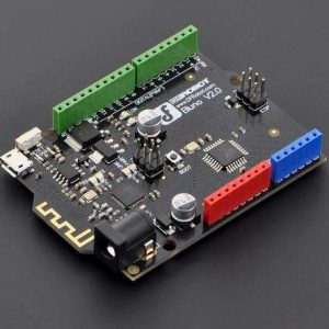
The ComMotion is an I2C controlled, 4 channel motor controller in an R3 shield format. The advantage of using I2C is that the shield only uses 2 pins. This leaves most of your pins free for use with other shields, sensors and circuits. The ComMotion shield can drive 4 DC brushed motors up to 2.5A continuous each with peak currents up to 4A per motor. Current monitoring is used to limit the maximum current for each motor. Each motor has an encoder input that can be used for precise speed control. Encoder feedback also gives the motor much more torque at low speeds.
Preset configurations allow you to control robots with either omni or mecanum wheels by sending the ComMotionshield only 3 simple values: Velocity, Angle and Rotation. The two ATmega328P onboard processors will then do the trigonometry required to calculate the correct speed for each individual motor.If encoders are not being used then the shield will still function normally but motor speed control will be the same as with standard motor drivers. Speed control will be less accurate and the motors will have much less torque at low speeds.Each processor has it’s own serial port broken out into an FTDI header. These serial ports can be used for GPS, Bluetooth and LCD modules while leaving your Arduino serial port free for uploading and debugging code. The serial port on MCU2 is also broken out into a socket for an XBEE or WiFly wireless transceiver with voltage translation circuitry and a dedicated 300mA, 3.3V regulator.
ComMotionSpecifications
- Processors: 2x ATmega328P (16MHz)
- Supply voltage: 6V – 16V
- Logic voltage: 5V @ 1000mA*
- Wireless support: Xbee / WiFly socket with voltage translation
- Xbee / WiFly power: 3.3V @ 300mA
- Battery monitor range: 0V – 17V
- Battery monitor resolution: ≈0.02V
- Analog Inputs: 5x 10bit (A3,A6 MCU1 – A3,A6,A7 MCU2)
- Motor drivers: 4x FET“H” bridge
- Motor current continuous: 2.5A (each motor)
- Motor current stall: 4A (each motor)
- Current monitor range: 0A – 5A (each motor)
- Current monitor resolution: ≈5mA (each motor)
- I2C bus voltage: 5V or 3.3V (selected by IO_REF pin)
- I2C bus speed: 100 kbit/s
- I2C addresses: 16 selectable pairs (software configurable)
- Serial ports: 2x 5V TTL logic (FTDI headers)
Out of the box
The ComMotionshield comes with demonstration software used in the Scamper robot kit. When you first turn it on it will play a tune if the demo mode is on or or beep a few times if it is off using all connected motors for speakers. If it has not received any data or commands from the I2C bus or a serial port by the time the tune is complete it will then run in demo mode. The demonstration program can be toggled on or off by pressing the reset button or cycling the power. Even if you are not using a Scamper robot this is a useful tool to determine if the board is functioning ok. Once the shield has received data or a command it will no longer default to demonstration mode unless you re-set the configuration to demonstration mode.
The ComMotion shield comes pre-programmed to work as an I2C controlled, 4 channel, smart motor controller. The term smart refers to the fact that the controller will use encoder inputs to try and maintain steady motor speeds regardless of the motors load. This allows the motors to be driven at low speeds and maintain full torque without stalling. If you are not using encoders then this feature can be disabled in the configuration. The controller will then behave like a standard motor controller.
Using chassis configurations
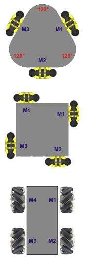
The ComMotion shield has 3 configurations programmed into it. When one of these configurations is selected then the shield will calculate the speed and direction of each motor for you based on three integers, velocity, angle and rotation.
When using any of these 3 pre-programmed configurations, the motors are always numbered in a clockwise direction as shown in the diagrams on the right. Match the motor numbers with the motor outputs on the shield. No matter which configuration you choose, test that the wiring is correct by trying to rotate. If a motor spins in the wrong direction then swap it’s wires around at the screw terminals.If you are using mecanum wheels then make sure they are orientated the same way as shown in the diagram.
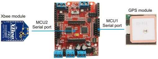
The ComMotion shield will accept commands from the serial port on MCU2 and send back all data to the serial port on MCU2 by default (mode 4). This means that if you install a Bluetooth, Xbee or WiFly module then the ComMotionshield can be controlled wirelessly without an Arduino or any other external processor and all serial data received from the serial port on MCU1 can be sent back through the serial port on MCU2.
In the example below, a pre-configured Xbee module is plugged into the ComMotion shield and a GPS module is connected to port 1. All data received from the GPS module will automatically be transmitted back through the Xbee module on port 2.
References