PULL UP RESISTORS
Let’s say I have a microcontroller (MCU) with one pin configured as an input. If I don’t connect anything to the pin, it is considered floating. This means the MCU might have a difficult time reading the state or voltage on the input pin. A pull-up or pull-down resistor will hold the pin to either a high or low state, while using a low amount of current.
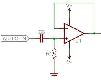
Pull-ups are common on most input logic lines, two-wire (I2C) lines, reset lines, etc. An application of a pull-up resistor is attaching a button to an input pin.
With a pull-up resistor, the input pin will read a high state when the button is open. When the button closes, it connects the input pin directly to ground, thus reading a low state. For this discussion we are ignoring the debounce of the button.
So what value resistor should you choose?
The short and easy answer is that you want a resistor value on the order of 10kOhm for the pull-up.
A low resistor value is called a strong pull-up, a high resistor value is called a weak pull-up.
The value of the pull-up resistor needs to be chosen to satisfy two conditions:
- When the button is pressed, the input pin is pulled low. The value of the resistor controls how much current you want to flow from VCC through the resistor R1, through the button, and then to ground.
- When the button is not pressed, the input pin is pulled high. The value of the pull-up resistor controls the voltage on the input pin.
For condition 1, you don’t want the resistor’s value too low. The lower the resistor, the more power will be used when the button is hit. You generally want a large resistor value, but not too large as to conflict with condition 2.
The general rule for condition 2 is to use a pull-up resistor (R1) that is an order of magnitude (1/10th) less than the input impedance (R2) of the input pin. An input pin on a microcontroller has an impedance that varies around 100k-1MOhm. For this discussion, impedance is just a fancy way of saying resistance and is represented by R2 in the picture above. So, when the button is not pressed, a very small amount of current flows from VCC through R1 and into the input pin. The pull-up resistor R1 and input pin impedance R2 divides the voltage, and this voltage needs to be high enough for the input pin to read a high state.
For example, if you use a 1MOhm resistor for the pull-up R1, and the input pin’s impedance R2 is on the order of 1MOhm, the voltage on the input pin is going to be around half of VCC and the microcontroller might not register the pin being in a high state. In other words, with increasing values for R1, the voltage on the input pin decreases and you don’t want it too low.
Keep in mind that many MCUs, like the ATmega328 on the Arduino, have internal pull-ups that can be enabled and disabled.
Another thing to point out is that the larger the resistance for the pull-up, the slower the pin is to respond to voltage changes. This is because the system that feeds the input pin is essentially a capacitor coupled with the pull-up resistor, thus forming a RC filter. And RC filters take some time to charge and discharge. If you have a really fast changing signal (like USB), a large pull-up can limit the speed at which the pin can reliably change state.
All of these factors play into the decision on what value pull-up resistor to use.
So Let’s See an Example
Let’s say you want to limit the current to exactly 1mA when the button is pressed in the circuit above, where Vcc = 5V. What resistor value should you use?
It is easy to show how to calculate the pull-up resistor using Ohm’s Law.
Rearrange the above equation with some simple algebra to solve for the resistor.Remember to convert all of your units into Volts, Amps and Ohms before calculating (e.g. 1mA = 0.001 Amps). The solution is to use a 5K Ohm restistor.
LED CURRENT LIMITING RESISTOR
Limiting current into an LED is very important. An LED behaves very differently to a resistor in circuit. Resistors behave linearly according to Ohm’s law: V = IR. For example, increase the voltage across a resistor, the current will increase proportionally, as long as the resistor’s value stays the same. Simple enough. LEDs do not behave in this way. They behave as a diode with a characteristic I-V curve that is different than a resistor.
For example, there is a specification for diodes called the characteristic (or recommended) forward voltage (usually between 1.5-4V for LEDs). You must reach the characteristic forward voltage to turn ‘on’ the diode or LED, but as you exceed the characteristic forward voltage, the LED’s resistance quickly drops off. Therefore, the LED will begin to draw a bunch of current and in some cases, burn out. A resistor is used in series with the LED to keep the current at a specific level called the characteristic (or recommended) forward current.
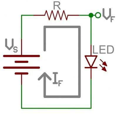
Using the circuit above, you will need to know three values in order to determine the current limiting resistor value.
i = LED forward current in Amps (found in the LED datasheet)
Vf = LED forward voltage drop in Volts (found in the LED datasheet)
Vs = supply voltage
Once you have obtained these three values, plug them into this equation to determine the current limiting resistor. Also, keep in mind these two concepts when referring to the circuit above.
- The current, i, coming out of the power source, through the resistor and LED, and back to ground is the same. (KCL)
- The voltage drop across the resistor, in addition to the forward voltage drop of the LED equals the supply voltage. (KVL)
Example 1
What current limiting resistor value should you use if you have one LED and want to power it with a supply voltage of Vs = 3.8V?
To calculate the current limiting resistor, you first need to look in the datasheet (always RTFM first!) for the LED’s recommended forward voltage and forward current specifications. In this example, they are 3.1V and 30mA respectively. Don’t forget to convert all of your units to Volts, Amps, or Ohms! e.g. 1mA = 0.001Amps
If you plug the values into the above equation, you get = 23.3 Ohms might be an odd value to find, so round up to the next highest common value.
Example 2
What if you wanted to power a high power LED? What should the power rating for the resistor be?
The resistor’s purpose is to limit current and thus uses some amount of power. You need to be sure the wattage (power) rating for your resistor is sufficient for the power being used.
Let’s say you are using the LED above with a supply voltage of 12V, an LED forward voltage of 3.9V, and a total forward current of 1400mA. What power rating should you choose for your resistor?
The resistor has a voltage drop and so does the LED. So, according to Kirchoff’s Voltage Law, if you solve for the voltage drop of the resistor, you get 8.1V. Now we have enough information to plug the numbers into the power equation (be sure to convert all units to Amps and Volts, e.g. 1400mA = 1.4A):
The calculated value is approximately 12 Watts. Generally, you should get a resistor wattage rating close to twice the calculated value. So a resistor in the neighborhood of 20-25 Watts would be sufficient. Also, keep in mind, a 20-25 Watt resistor will be pretty huge!